A fire door closer is not simply a device that moves a door toward the frame. It must generate enough controlled closing moment to move the leaf through its full arc, overcome hinge friction, air-pressure differences and seal resistance, and finally provide enough latching action for the latchbolt to engage. If any part of that sequence is incomplete, the labeled opening may not perform as intended.
This technical guide explains how to select and apply a UL listed door closer within a fire door assembly. It examines the relationship between UL 10C certification, NFPA 80 operational requirements, ANSI/BHMA A156.4 performance testing, mounting geometry, spring power, hydraulic control and field verification. The focus is the engineering and compliance logic behind the closer—not supplier comparison or purchasing strategy.
QUICK TECHNICAL ANSWER: Verify the exact closer model within the current listing, match its application and fire-rating scope to the opening, calculate the effect of door size and mounting efficiency, then adjust and test the complete opening until it closes and positively latches from every required position. |

1. What a Door Closer Contributes to a Fire Door Assembly
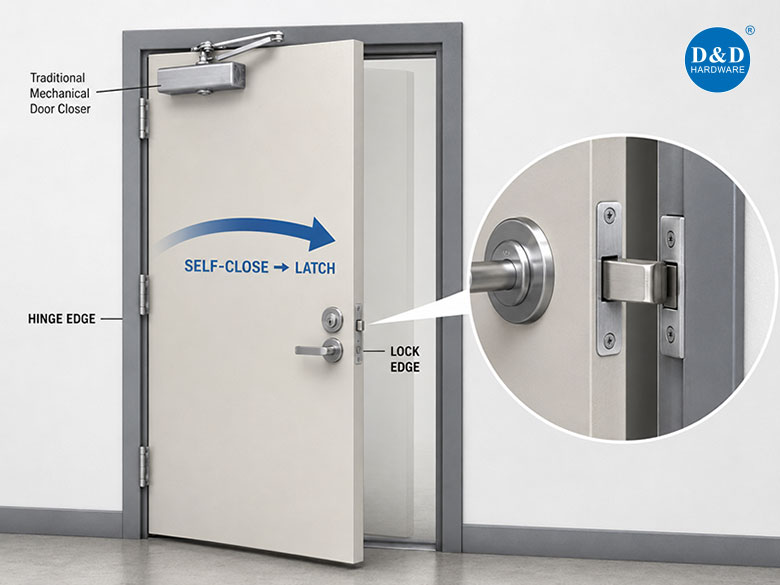
The closer supplies the energy needed to return a swinging door to the closed position. The latching hardware then retains the door in the frame. These are separate functions: a closer can move the leaf without achieving positive latching, and a correctly specified lock cannot latch if the closer leaves the door short of the strike.
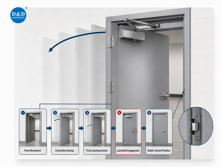
For fire door assembly hardware, the relevant performance chain is: free door movement, controlled sweep, sufficient final latching action, latchbolt engagement and stable closed-door position. Binding hinges, a misaligned frame, excessive seal compression or pressure imbalance can interrupt the chain even when the closer itself is correctly listed.
2. UL 10C, NFPA 80 and ANSI/BHMA A156.4: Different Technical Roles
Document / Standard | Technical Role | What to Verify |
UL 10C | Positive-pressure fire testing of door assemblies and the basis for applicable product ertification. | Exact model, file number, rating scope, approved application and marking. |
NFPA 80 | Installation, inspection, testing and maintenance framework for fire door assemblies. | The door closes, latches and is free of conditions that interfere with operation. |
ANSI/BHMA A156.4 | Performance requirements and test methods for door controls, including closers. | Declared grade, cycle performance, functions and manufacturer data for the model. |
Accessibility standard adopted by the project | Controls aspects such as closing time and, where applicable, opening force. | The locally adopted edition and any fire-door exceptions or requirements. |
These documents should not be treated as interchangeable. A closer may meet an ANSI/BHMA performance grade without being listed for a fire door application. Conversely, a UL 10C listing does not remove the need to configure the closer so the opening meets operational and accessibility requirements.
3. How to Verify a UL-Listed Door Closer
A general UL logo in a catalog is not sufficient evidence for a specific application. Verification is model-specific. Compare the closer body marking, model designation, arm or accessory configuration, installation instructions and current listing information. Pay attention to limitations for door construction, mounting position, opening size and optional functions.
· Identify the exact closer model and manufacturer.
· Confirm the UL file number and the applicable certification category.
· Check the fire-rating scope and any stated application limitations.
· Confirm that the selected arm, bracket and mounting position are permitted.
· Use the installation template and fasteners specified for the door and frame construction.
D&D UL 10C Door Closer Example
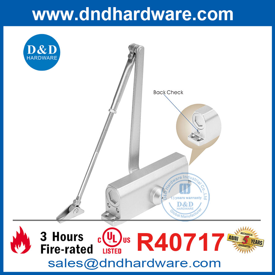
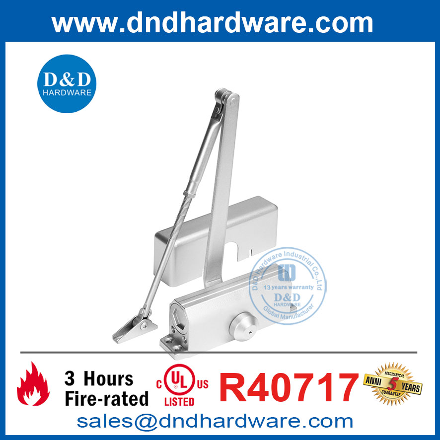
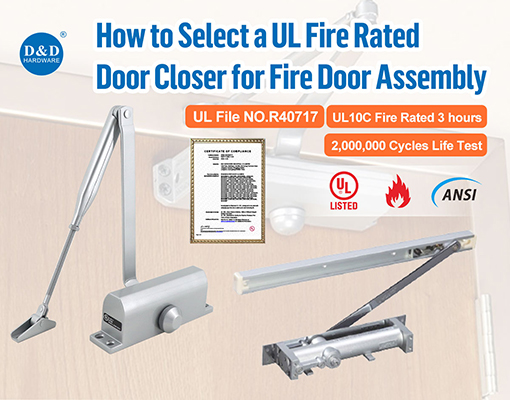
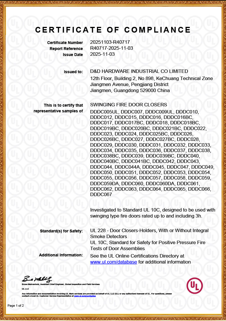
D&D UL-listed door closers are certified to UL 10C for up to 3 hours under File No. R40717. The exact model, arm configuration and application must still be checked within the current listing scope. This model-level verification is the correct way for a fire door hardware manufacturer, specifier or installer to connect a certification claim to an actual opening.
4. Door Size, Mass and Required Closing Moment
Closer selection is governed by torque rather than door weight alone. The resisting moment at the hinge axis increases with leaf width because the effective lever arm becomes longer. A wide door can therefore require more closing moment than a narrower door of similar mass. Wind, stack pressure, HVAC pressure, gasket compression, latch resistance and hinge condition add further resistance.
Published closer-size charts are the starting point. Final selection must use the manufacturer's model-specific chart and include the mounting configuration. Do not assume that a nominal size or an adjustable Size 1–6 range produces identical effective force in every mounting arrangement.
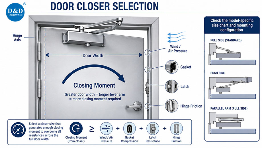
ENGINEERING PRINCIPLE: Available latching margin = closer output at the final arc minus the combined resistance of hinges, seals, latch engagement and pressure across the door. A door that closes only when released from 90° may still lack sufficient margin to close from a partially open position. |
5. Mounting Geometry Changes Effective Power
Configuration | Typical Side | Mechanical / Application Effect |
Regular arm | Pull side | Efficient conventional geometry; the arm projects from the door face when closed. |
Parallel arm | Push side | Arm folds parallel to the door; commonly preferred where projection or abuse is a concern, but geometry can reduce effective closing power compared with regular-arm mounting. |
Top jamb | Push side | Closer body mounts to the frame head; useful where the door top rail cannot accept the body. Frame depth and reveal affect geometry. |
The mounting template is part of the technical application. Moving the body or shoe to “make it fit” changes arm geometry, opening angle and available torque. On a rated opening, field relocation should not be improvised. Confirm the approved template, reinforcement and fasteners before drilling.

6. Understanding the Hydraulic Control Zones
Most surface closers combine a spring with a hydraulic circuit. The spring stores energy as the door opens. Controlled fluid flow regulates how that energy is released during closing. Valve names vary by model, but four functions are common:
Control | Typical Zone / Function | Technical Caution |
Sweep speed | Main closing arc, commonly from the open position toward the final 10°–15°. | Too fast can create impact; too slow may produce poor usability or allow pressure changes to stall the leaf. |
Latch speed | Final arc before closed position. | Must provide controlled movement with enough momentum and spring torque to engage the latch. |
Backcheck | Opening arc near the maximum opening angle. | Resists abrupt opening; it is not a door stop and should not be adjusted to prevent normal opening. |
Delayed action | Optional controlled delay during part of the closing cycle. | Use only where the specific closer and fire-door application permit it. |
Adjustment valves should be changed in small increments. Excessive loosening can damage the hydraulic control or permit leakage. Spring power and hydraulic speed are different variables: increasing speed does not create additional spring torque, and increasing spring power does not correct a blocked hydraulic passage or mechanical bind.
7. Self-Closing and Positive Latching
A compliant result is not “the door reaches the frame.” The leaf must close to the position at which the latching hardware engages. Functional testing should include the full-open position and representative partially open positions because available spring energy and door momentum differ across the swing.
· Open the door fully, release it without assistance and observe the complete closing cycle.
· Repeat from a partially open position, including a position only a few inches from closed.
· Confirm that the latchbolt enters the strike and retains the door.
· Check for hinge bind, frame contact, floor contact, seal drag and interference from adjoining leaves.
· Repeat after changes to seals, latch adjustment, HVAC balancing or closer settings.
8. Accessibility and Fire-Door Performance Must Be Balanced
Reducing spring power can lower opening resistance, but it also reduces the energy available for closing and latching. The correct adjustment is therefore not the lowest possible spring setting; it is the lowest setting that still provides reliable operation while meeting the accessibility requirements adopted for the project.
Under the 2010 ADA Standards, a door equipped with a closer is generally required to take at least five seconds to move from 90° open to 12° from the latch. Opening-force requirements depend on door type and the adopted code. Fire doors are not appropriately evaluated by applying a single universal force number without checking the governing accessibility provisions and local amendments.
9. Hold-Open Functions on Fire Doors
A manual mechanical hold-open can defeat the closing function of a fire door. Where a rated opening is intended to remain open during normal use, the hold-open or release arrangement must be specifically permitted, listed for the application and connected so the door is released by the required fire-protection signal. The closer must then close and latch the released door.
This is a system function involving the closing device, releasing device, detection or alarm interface, power condition and latching hardware. Verification should include loss-of-power or alarm-release behavior as required by the project design and adopted codes.
10. Installation Conditions That Change Closer Performance
Observed Condition | Why It Matters | Technical Check |
Door or frame lacks reinforcement | Fasteners can loosen or the mounting surface can deform. | Confirm reinforcement, through-bolts or listed fastener method. |
Incorrect arm preload | Reduces available closing moment or changes the operating arc. | Set arm geometry exactly as shown on the template. |
Hinge bind or misalignment | Consumes closer torque throughout the swing. | Test free movement before increasing spring power. |
High seal or latch resistance | Prevents the final few degrees of travel. | Align the strike and verify seal compression. |
HVAC / stack pressure | Creates a pressure force across the leaf. | Test under normal building operating conditions. |
Temperature change | Changes hydraulic-fluid viscosity and door behavior. | Recheck seasonal or exterior applications after stabilization. |

11. Field Adjustment Sequence
1. Confirm that the door, frame, hinges and latch operate freely before adjusting the closer.
2. Verify body position, arm geometry, preload, fasteners and opening angle against the template.
3. Set spring power according to the model chart, door size and mounting configuration.
4. Adjust sweep speed in small increments.
5. Adjust latch speed so the door engages the latch without uncontrolled impact.
6. Set backcheck only after the normal opening and closing cycle is stable.
7. Measure applicable closing time and opening force using the project's adopted accessibility criteria.
8. Test closing and latching from multiple opening positions under normal HVAC conditions.
9. Record the final model, mounting, settings and test result for maintenance reference.
12. Troubleshooting a Fire Door That Will Not Latch
Symptom | Likely Cause | Diagnostic Direction |
Stops before the frame | Hinge bind, seal drag, floor contact, low spring setting or adverse pressure. | Disconnect the closer arm only if safe and permitted, check free swing, then isolate mechanical resistance. |
Reaches frame but latch does not engage | Strike misalignment, insufficient latch action or excessive seal compression. | Inspect latch/strike geometry before increasing speed. |
Slams through the main arc | Sweep valve too open, damaged hydraulics or incorrect adjustment. | Restore controlled sweep; inspect for leakage. |
Closes from 90° but not from 10° | Insufficient final torque, latch resistance or incorrect arm preload. | Check preload, spring setting and final-arc resistance. |
Performance changes with HVAC on | Pressure differential across the door. | Measure and coordinate building pressure; avoid using speed alone as the correction. |
Closer body or shoe moves | Inadequate reinforcement or loose fasteners. | Stop adjustment and correct attachment method. |
13. Technical Selection Checklist
· Exact closer model verified within the current UL listing.
· UL file number, fire-rating scope and product marking confirmed.
· Door construction, size, mass and swing conditions identified.
· Mounting configuration and template approved for the application.
· Spring range accounts for mounting efficiency, pressure and latch resistance.
· Sweep, latch, backcheck and optional controls match the functional requirement.
· Hold-open or delayed-action function is permitted for the rated opening.
· Reinforcement, fasteners and arm geometry comply with instructions.
· Closing time and opening force are checked against adopted accessibility requirements.
· The installed door closes and positively latches from all required positions.

Frequently Asked Technical Questions
Is every ANSI/BHMA A156.4 door closer suitable for a fire door?
No. ANSI/BHMA A156.4 addresses door-control performance and testing. Suitability for a fire door application must be established through the applicable listing and installation conditions. Both pieces of information matter.
Does a three-hour rating mean the closer can be used on any three-hour opening?
No. The rating is only one part of the application. Verify the exact model, listing scope, door construction, arm configuration, mounting and installation limitations.
Can latch speed be increased until a difficult door latches?
Only after mechanical causes have been checked. Excessive speed can mask strike misalignment, hinge bind, seal resistance or pressure problems and may create unsafe impact. Correct the resistance first, then tune the hydraulic controls.
Why does a parallel-arm installation sometimes need more spring power?
Parallel-arm geometry generally provides less mechanical efficiency than regular-arm geometry. Manufacturer sizing tables often account for this difference; the model-specific chart and template govern.
What makes a fire rated door closer technically successful?
The closer must be correctly listed and applied, securely mounted, appropriately powered and adjusted so the complete door moves freely, closes at a controlled rate and positively latches under actual building conditions.
Contact us Now:
Contact: David Jian
Mob:0086-139 2903 7292
Email: David@dndhardware.com, sales@dndhardware.com,
Contact: Jobby Zhang
Mob:0086-137 2599 9617
Email: jobby@dndhardware.com
D&D HARDWARE INDUSTRIAL CO.,LTD
ADD:12th Floor, Building 2, No.898, KeChuang Technical Zone, Jiangmen Avenue, Pengjiang District, Jiangmen City, Guangdong, China (Postcode:529000)
https://www.dndhardware.com
Tel: +86-750-3856396
Fax: +86-750-3856395


 English